Download Experiment 8: Arithmetic Operation Circuit and more Lab Reports Digital Logic Design and Programming in PDF only on Docsity!
The Papua New Guinea University of Technology
Department of Electrical & Communication Engineering
EE221 Digital Logic Systems
Experiment 8:
Arithmetic Operation Circuit
Name: Felix Komolong
ID #: 20600308
S/CODE: EE
C/CODE: BSAP/
GROUP#: 3
Introduction
Digital computers and calculators perform various arithmetic operations on numbers that are represented in binary form. These operations are all performed in the arithmetic logic unit of a computer. Logic gates and flip-flops are combined in the arithmetic logic unit so that they can add, subtract, multiply and divide numbers. These circuits perform arithmetic operations at speeds that are not humanly possible. In this lab, 3 different adder circuits were observed. The circuits were a Half Adder, A Full Adder and a Carry Look-Ahead Adder.
Background
An arithmetic circuit is a set of gates with a separate set of inputs for each number that has to be processed. The gates are connected so as to carry out an arithmetic action and the outputs of the gate circuit are the digits of the result. Half adder is a combinational circuit, which performs the addition of two binary numbers A and B are of single bit. It produces two outputs sum, S & carry, C. Full adder is a combinational circuit, which performs the addition of three bits A, B and Cin. Where, A & B are the two parallel significant bits and Cin is the carry bit, which is generated from previous stage. This Full adder also produces two outputs sum, S & carry, Cout, which are similar to Half adder. In the concept of carry look-ahead circuits, the bits that are necessary for addition are immediately available. Whereas every adder section needs to hold its time for the arrival of carry from the previous adder block. Because of this, it takes more time to produce SUM and CARRY as each section in the circuit waits for the arrival of input. To overcome the delay in ripple carries adder, a carry-look ahead adder was introduced.
Apparatus or Equipment
- Digital-analog training system M21-
- Circuit Board DTS- ◦ 3E ◦ 3B ◦ 3A ◦ 3C ◦ 3D
- Circuit Board DTS- ◦ 2E
Objectives
- Master the design method of combinational logic circuits
- Master half adder, full adder design
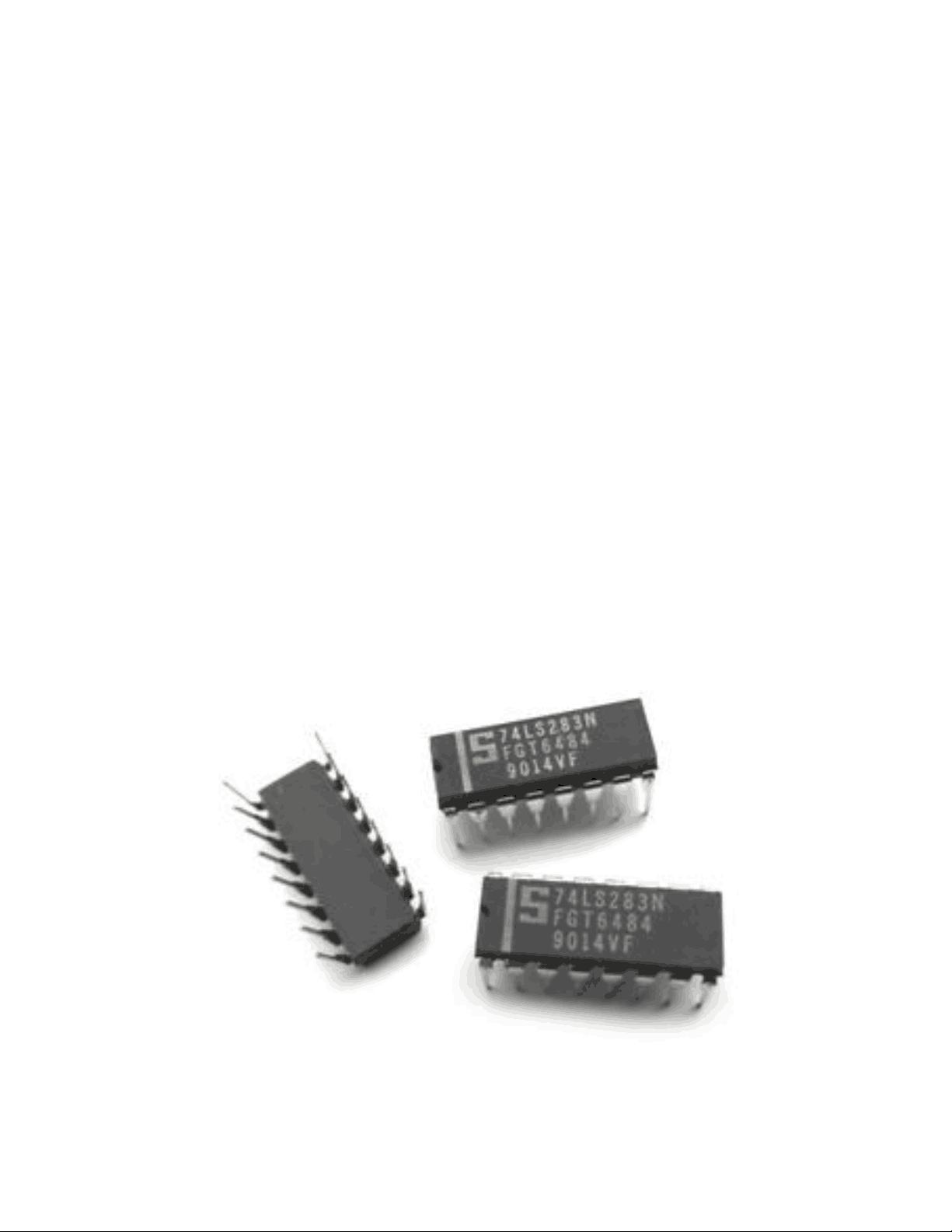
b) We then used a dedicated integrate circuit 74LS283 TTL to achieve a full adder with internal carry look-ahead pin functions as follows:
- A1 – A 4 Operand inputs, switches 7-
- B1 – B 4 Operand B inputs, switches 3-
- C 0 Carry input (goes to input of C 4 )
- S 1 – S 4 Sum ouputs, LED 15, 13, 11, 9
- C 4 Carry output c) Lastly, we set up the carry look-ahead adder circuit as shown in the diagram below. The results of the different conditions were recorded.
Results
Truth Tables:
1. 3-bit binary data parity bit Table 1 A B Sum Carry 0 0 0 0 0 1 1 0 1 0 1 0 1 1 0 1
2. a) Full-Adder Inputs Outputs A B C 0 S C 0 0 0 0 0 0 0 1 1 0 0 1 0 1 0 0 1 1 0 1 1 0 0 1 0 1 0 1 0 1 1 1 0 0 1 1 1 1 1 1 2. b) Integrated full adder Input Output A3 A2 A1 A0 B3 B2 B1 B0 Decimal Value S3 S2 S1 S0 Decimal Value 0 0 0 1 0 0 0 1 1 + 1 0 0 1 0 2 0 1 1 0 0 0 1 0 6 + 2 1 0 0 0 8 1 0 1 0 0 1 0 1 10 + 5 1 1 1 1 15 1 1 1 0 0 0 0 0 14 + 0 1 1 1 0 14 2. c) Carry look-ahead adder Inputs Outputs AI BI CI-1 Si Pi Gi 0 0 0 0 0 0 0 0 1 1 0 0 0 1 0 1 1 0 0 1 1 0 1 0 1 0 0 1 1 0 1 0 1 0 1 0 1 1 0 0 0 1 1 1 1 1 0 1
Discussion
1. Half Adder When two digits are added together, the result consists of two parts, known as the SUM and the CARRY. Since there are only four possible combinations of two binary digits, one combination produces a carry. 2. a) Full-Adder A full adder circuit can be constructed using two half adders. Two of the three inputs are connected to the first half adder which produces a partial sum and partial carry output. The partial sum is fed to the second half adder along with the third of the original inputs. This causes the final sum to be produced and also another partial carry. 2. b) Integrated full adder The 74LS283 is a high-speed 4-Bit Binary Full Adder with internal carry look-ahead. It accepts two 4- bit binary words (A1–A4, B1–B4) and a Carry Input (C0). It generates the binary Sum outputs (S1–S4) and the Carry Output (C4) from the most significant bit. The LS283 operates with either active HIGH or active LOW operands (positive or negative logic). 2. c) Carry look-ahead adder The carry propagates equation is Pi = Ai XOR Bi and the carry generate is Gi = Ai*Bi. Gi delivers carry only when both the inputs Ai and Bi are 1 without considering the input carry. Pi is related to the carry propagation from Ci to Ci+1.
Conclusion
For this lab, we looked at the application of a combinational logic circuit that performed some arithmetic functions. The objectives that we set out to master were helpful in understanding the process behind how some simple math functions can be performed with binary data using logic gates. We noted that the half adder generates sum & carry by adding two binary inputs whereas the full adder is used to generate sum & carry by adding three binary inputs. Half adder’s operate on 2-two inputs of 1-bit, whereas the Full adder’s operate on three inputs of 1-bit. Half adder is used in different electronic devices for evaluating the addition whereas the full adder is used in digital processors for the addition of a long bit. The adder’s are similar in the fact that they do not use any memory element such as sequential circuits. It was tricky at first trying to understand the carry output and input but as we worked through the experiment the logic behind it became more clear. All in all, the lab was successful.
Reference:
- PREETHIGN, et al. “Half Adder and Full Adder Circuit with Truth Tables.” ElPoCus , 28 Oct. 2020, https://www.elpocus.org/half-adder-and-full-adder/.
- “Experiment 8. Arithmetic Circuits” DCL 7000 Laboratory Manual.
- Digital Arithmetic Circuits , https://www.tutorialpoint.com/digital_circuits/digital_arithmetic_circuit.htm.