Download Experiment with Direct Current - Laboratory | PHYSICS 4BL and more Lab Reports Physics in PDF only on Docsity!
Experiments with Direct Currents
NAME Xun Jia UID 003180159
INSTROCTOR Reiner Stenzel LAB SECTION
LAB DATE 04/26/
LAB PARTNERS
z INTRODUCTION
The experiments about direct current have broad applications. In these experiments, the basic physical law, Ohmís Law, plays an important role. For the linear elements in a circuit, the Ohmís Law states that the ratio of the voltage across this element to its current is a constant, which is called resistance. Traditionally, it is thought that the resistance of an element depends only on its material and the geometrical parameter. However, with the development of modern science, more and more special kinds of materials are discovered. For some elements, the resistance is very sensitive to many other parameters, such as the temperature, the current ect.. These special properties allow us to produce many instruments which can be found everywhere all around this world. In this experiment, we will first verify Ohmís Law for a basic linear element, a resistor. And then learn some major applications of Ohmís Law in the fields of direct current theory.
z THEORY
A. Experiments on Linear Elements
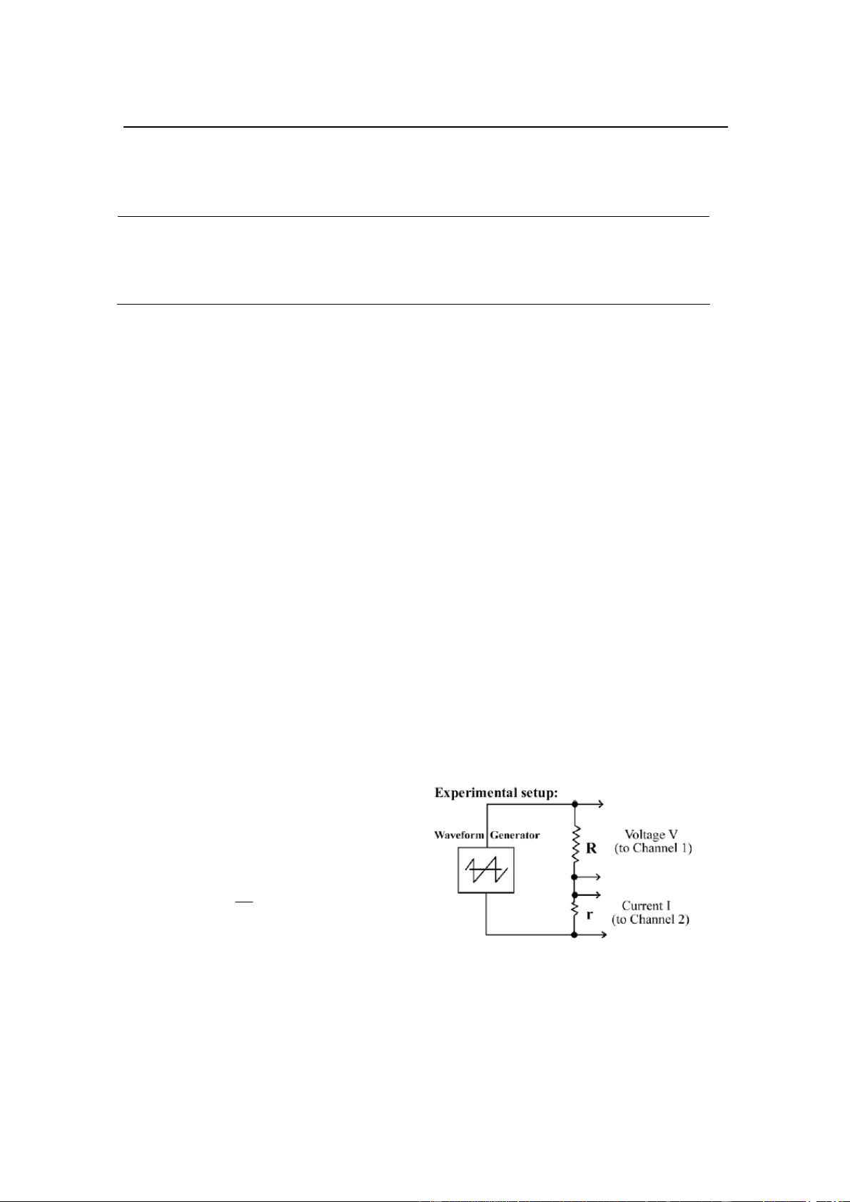
According to the Ohmís Law, in Fig.1, the voltage V , and current I on resistor R satisfy this relation:
V R = IR R
Since the resistors R and r are connected in series, we have:
R
r
V
V R = IrR = r
If we use the ADC system to acquire the voltage signal VR and Vr at the same time, from Vr and r , we can obtain the current I (^) R flowing in the resistor R. According to Ohmís Law, V (^) R and I (^) R have a linear relation, thus by drawing the figure I (^) R VS V (^) R , we can verify Ohmís Law.
Fig. 1 Experiment setup for part A
B. Experiments on Nonlinear Elements
For the nonlinear element, its resistance R will not be a constant. In this experiment, the Zener diode is a typical kind of nonlinear element, and its resistance R is current dependent. In Fig. 1, we substitute the resistor R by a Zener diode, then we can acquire its voltage and current signal at the same time, thus we will have a direct sense about the I-V relation of this nonlinear element.
C. Conductivity of Matters
C.1 Conductivity of copper:
If the length of a wire is L , its radius is r , theoretically, the resistance R between its two ends are given by this equation:
2
r
L
R
where σ is the conductivity of this material. Thus if we can measure the resistance R , and the geometrical parameters as well, we are able to get the conductivity of this material.
C.2 Conductivity of water:
Impure water is a kind of conductor. When we plug two electrodes in the water, the DC resistance R and the capacitance C of this system have the relation:
RC =ε 0 σ
where σ is the conductivity of water, and ε 0 is a constant. The DC resistance can be obtained in our experiment by Ohmís Law, and the capacitance can be calculated theoretically as:
cosh ( / 2 ) ln( /^ )
0 1
0
d r
l
d r
C = πε^ l ≅^ πε
−
where d is the center distance between two electrodes, l is the length of each electrode, and r is the radius of each electrode. Then we can calculate the conductivity of water.
D. Direct Current Circuits
D.1 Internal resistance of Ampere meters
Ideal Ampere meter should have zero internal resistance, however, each real Ampere meter has internal resistance, which is very small and can be ignored in some cases. In this experiment, we can use Ohm meter to measure the internal resistance of an analog Ampere meter directly.
D.2 Potentiometer
In Fig. 2, a potentiometer forms a continuously variable voltage divider. If we apply a DC voltage to the input of a potentiometer, by changing the position of its knob, the output voltage will change, ranging from 0V to the input voltage 10V. If this potential meter is linear, the output voltage Vout and the position, which is indicated by a angle α have this
Fig. 2 Experiment setup for part D.
A bridge circuit is shown in Fig. 4. If we apply a voltage V (^) in to the point A and B , and use a voltmeter to measure the voltage between the points C and D , when this voltage vanishes, we call this circuit is balanced. From Ohmís Law, we have:
3 4
4
1 2
2
R R
V V R
R R
V R
V
DB in
in CB
When the circuit is balanced, which implies that V (^) CB=V (^) DB , thus the condition for this circuit to be balanced can be written as:
4
3 2
1
R
R
R
R
If R 1 =R 3 , R 2 is the resistance we want to measure, and R 4 is variable, then when we change the resistance R 4 until this circuit is balanced, then we can get resistance of R 2.
D.6 Internal resistance of battery
A battery has internal resistance of a certain number, we can use the circuit shown in Fig. 5 to measure it. With the help of multimeter, we can get the open loop voltage V 0 , then when we construct the circuit as in Fig. 5, according to the Ohmís Law, the voltage across the load resistance Rload should be:
load
load
R R
V VR
int
0
Thus, the internal resistance of the battery can be expressed as:
V
R R V^ V
load
int
z PROCEDURE
a. In part a, use the ADC to acquire the I-V curve of a resistance, draw the I-V curve, then calculate the real value of the resistance, and verify Ohmís Law. b. In part b, use the ADC to acquire the I-V curve of a diode, and then draw the I-V curve. c. In part c, we did as following:
Fig. 4 The bridge circuit in part D.
Fig. 5 The setup in part D.
- Measure the resistance of the copper wire using the multimeter, then use the data provided in the lab manual to calculate the conductivity of copper.
- Apply a voltage to the parallel-wire electrodes, and measure both the voltage and the current. Calculate the resistance between these two electrodes, and then calculate the conductivity of water. d. In part d, we did as following:
- Measure the internal resistance of an analog current meter by using a digital multimeter.
- Setup a potentiometer and measure the output voltage at different angles (every 10 ∞), then draw a figure to show the relation between the output voltage and the angle. Calculate the parameter η= V/ α.
- Measure the resistance of each resistor, and the equivalent resistance, then verify the relation about the equivalent resistance.
- Measure the resistance of one resistor and the equivalent input resistance. Compare with theoretical value. Then measure the voltage drop at each element of the chain, compare with the theoretical values.
- Setup a bridge circuit, and balance it. Use this circuit to measure the resistance of the thermistor at room temperature.
- Measure the open-loop voltage of a battery, then apply a load resistance Rl and measure the voltage across it. Calculate the internal resistance of the battery.
z DATA
A. Experiments on Linear Elements
V (^) PK-PK = 18.8 V f = 7.19 Hz R 1 = 55.1 KΩ R 2 = 38.4 KΩ
B. Experiments on Nonlinear Elements
V (^) PK-PK = 18.8 V f = 8.40 Hz R 1 = 0.814 KΩ
C. Conductivity of Matters
C.1 Conductivity of copper:
R = 10.8 Ω
C.2 Conductivity of water:
V = 10.97 V I = 22.3 mA
D. Direct Current Circuits
D.1 Internal resistance of Ampere meters
R = 2.90 KΩ
D.2 Potentiometer
V = 10.97 V
Refer to Table 1 on next page.
D.3 Resistors in series and in parallel
R 1 = 55.1 KΩ R 2 = 38.4 KΩ R 3 = 47.1 KΩ
B. Experiments on Nonlinear Elements
See Fig. 7 for main results. For the diode, we can not get a linear relation between the current and the voltage, since diode is a nonlinear element.
Fig. 6 The I-V relation for a resistor
Fig. 7 The I-V relation for a diode
C. Conductivity of Matters
C.1 Conductivity of copper:
R = 10.8 Ω
From the Lab Manual, we find the geometrical parameters are: d = 20.1 mils = 5.10E-4 m l = 409 feet = 125 m So: σ = 4l/(πd 2 R) = 5.66E7 m -1Ω- Compare with theoretical value: σe = 5.96 E7 m -1Ω- Our result from experiment has an error of 5%
C.2 Conductivity of water:
V = 10.97 V I = 22.3 mA Thus: R = V/I = 492 Ω Then this resistance implies that the conductivity of water is: σ = 3.88E-2 m-1Ω- Since the conductivity of water depends on the chemical component in it, such as Ca+, Na+, we can not compare this experiment value with theoretical value.
D. Direct Current Circuits
D.1 Internal resistance of Ampere meters
R = 2.90 KΩ
This is quite a big resistance, thus when we want to use this ampere meter to measure a current in a circuit, the resistance of this circuit must be much lager than this internal resistance, otherwise, we can not get accurate value.
D.2 Potentiometer
The relation between output voltage and the angle is shown in Fig. 8. By linear regression, we got this function: Vout (V) = -1.92 + 0.0460 α (deg) r = 0. The correlation coefficient r is so close to 1 that we can conclude that the relation between the output voltage and the angle is a linear relation, however, this relation only holds in a certain range ( 40 ∫ <α < 280 ∫ ). Moreover, from the linear regression, we have: η = V (^) out / α = 0.0460 V/deg
D.3 Resistors in series and in parallel
R 1 = 55.1 KΩ R 2 = 38.4 KΩ R 3 = 47.1 KΩ
R (^) e = 76.7 KΩ Theoretically, the equivalent resistance should be: Ret = R 1 + R 2 R 3 / (R 2 +R 3 ) = 76.2 KΩ This value is very close to the resistance we got from experiment, and the experiment has an
R 1 = R 2
This implies that the resistance to be measured is also: R 3 = R 4 = 835 Ω
D.6 Internal resistance of battery
V 0 = 3.05 V V = 1.54 V R = 20.4 Ω
Thus, the internal resistance of the battery is: Rint = R(V 0 -V)/V = 20.0Ω This is a not large resistance, so generally, when we use this battery, we do not need to consider the impact of the batteryís internal resistance, however, when the load resistance is comparable with this internal resistance, we have to take this internal resistance into account.
z DISSCUSSION AND CONCLUSION
In this experiment, we first measured the I-V relation for linear and nonlinear elements, and for the linear elements (resistors), our result consisted with Ohmís Law, which is the basic theory of DC circuit. In the third part, we measured the electric conductivity of two kinds of materials, copper and water, and our result gave a same result as theoretical value. In the last part, those experiment results were also satisfied the theoretical requirements. In conclusion, during this experiment, we not only learned how to carry out the experiments about DC circuit, but also got a direct sense about the basic theories in this field. Moreover, our experiment result is quite good, and this is really a successful lab.