Download Object Oriented analysis and more Study notes Object Oriented Analysis and Design in PDF only on Docsity!
Chapter 2: Object Oriented Analysis
1.0 Building Domain/Conceptual Models
The Object oriented analysis can be performed at different level of abstractions such as:
- ENTERPRISE LEVEL
- BUSINESS AREA LEVEL
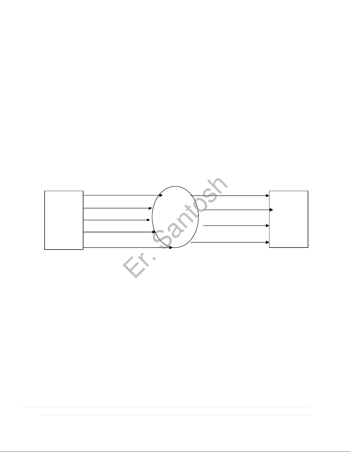
- APPLICATION LEVEL The analysis we are dealing is the middle level of abstraction i.e Business Area level (Domain level) .One of the most important activities involved is domain analysis, which is performed when an organization wants to create a library of reusable classes that will be broadly applicable to an entire category of applications. The domain analysis can be viewed as an umbrella activity for the software process, which states that domain analysis is an ongoing software engineering activity that is not connected to any one software project. The immediately apparent benefits derived from the reuse are consistency, and familiarity. Patterns within the software will become more consistent, leading to better maintainability. The Fig below shows input and output of domain analysis:
Fig 1: Input/ Output diagram for domain analysis
A domain model is the most important and classic model in OO analysis. It illustrates noteworthy concepts in a domain. It can act as a source of inspiration for designing some software objects and will be an input to several artifacts explored in the case studies. This chapter also shows the value of OOA/D knowledge over UML notation; the basic notation is trivial, but there are subtle modeling guidelines for a useful model expertise can take weeks or
months.
A domain model is a visual representation of conceptual classes or real-situation objects in a domain. Domain models have also been called conceptual models (the term used in the first edition of this book), domain object models , and analysis object models.
In the UP, the term "Domain Model" means a representation of real-situation conceptual classes, not of software objects. The term does not mean a set of diagrams describing software classes, the domain layer of a software architecture, or software objects with responsibilities.
Sources of domain knowledge
Domain Analysis
Domain Analysis Model
Technical Literature
ExistingApplications Customer Surveys Expert Advice
Current/Future Requirements
Domain Language
Functional Models
Reuse Standards
Class Taxonomy
Er. Santosh
More precisely, the UP Domain Model is a specialization of the UP Business Object Model (BOM) "focusing on explaining 'things' and products important to a business domain". That is, a Domain Model focuses on one domain, such as POS related things. Applying UML notation , a domain model is illustrated with a set of class diagrams in which no operations (method signatures) are defined. It provides a conceptual perspective. It may show: domain objects or conceptual classes associations between conceptual classes attributes of conceptual classes
Fig 2: Simple Domain class model The goal of the domain analysis, as mentioned above ,to find or create those classes that are broadly applicable ,so that they may be reused ,is characterized by a number of steps as enumerated below: a. Define the domain to be investigated b. Categorize the items extracted from the domain c. Collect a representative sample of applications in the domain d. Analyze each application in the sample e. Develop an analysis model for the objects The responsibility of domain analysis falls on the domain analyst. Besides the above steps ,the domain analyst should also create a set of reuse guidelines and develop an example that illustrates how the domain objects could be used to create a new application.
Er. Santosh
What are Two Traditional Meanings of "Domain Model"?
"Domain Model" is a conceptual perspective of objects in a real situation of the world, not a software perspective. But the term is overloaded; it also has been to mean "the domain layer of software objects." That is, the layer of software objects below the presentation or UI layer that is composed of domain objects software objects that represent things in the problem domain space with related "business logic" or "domain logic" methods. For example, a Board software class with a getSquare method.
What are Conceptual Classes?
The domain model illustrates conceptual classes or vocabulary in the domain. Informally, a conceptual class is an idea, thing, or object. More formally, a conceptual class may be considered in terms of its symbol, intension, and extension (see Figure 5). Symbol words or images representing a conceptual class. Intension the definition of a conceptual class. Extension the set of examples to which the conceptual class applies.
Fig 5: A conceptual class has a symbol, intension, and extension.
For example, consider the conceptual class for the event of a purchase transaction. I may choose to name it by the (English) symbol Sale. The intension of a Sale may state that it "represents the
Er. Santosh
event of a purchase transaction, and has a date and time." The extension of Sale is all the examples of sales; in other words, the set of all sale instances in the universe.
Are Domain and Data Models the Same Thing?
A domain model is not a data model (which by definition shows persistent data to be stored somewhere), so do not exclude a class simply because the requirements don't indicate any obvious need to remember information about it (a criterion common in data modeling for relational database design, but not relevant to domain modeling) or because the conceptual class has no attributes. For example, it's valid to have attributed less conceptual classes, or conceptual classes that have a purely behavioral role in the domain instead of an information role.
How to Create a Domain Model?
Bounded by the current iteration requirements under design:
1. Find the conceptual classes (see a following guideline). 2. Draw them as classes in a UML class diagram.
3. Add associations and attributes.
How to Find Conceptual Classes?
What are Three Strategies to Find Conceptual Classes?
1. Reuse or modify existing models. a. This is the first, best, and usually easiest approach, and where I will start if I can. There are published, well-crafted domain models and data models (which can be modified into domain models) for many common domains, such as inventory, finance, health, and so forth.. **2. Use a category list.
- Identify noun phrases.** Reusing existing models is excellent, but outside our scope. The second method, using a category list, is also useful.
Method 2: Use a Category List
We can kick-start the creation of a domain model by making a list of candidate conceptual classes. Table 9.1 contains many common categories that are usually worth considering, with an emphasis on business information system needs. The guidelines also suggest some priorities in the analysis. Examples are drawn from the 1) POS, 2) Monopoly, and 3) airline reservation domains.
Er. Santosh
Method 3: Finding Conceptual Classes with Noun Phrase Identification
Another useful technique (because of its simplicity) suggested in is linguistic analysis : Identify the nouns and noun phrases in textual descriptions of a domain, and consider them as candidate conceptual classes or attributes. Nevertheless, linguistic analysis is another source of inspiration. The fully dressed use cases are an excellent description to draw from for this analysis. For example, the current scenario of the Process Sale use case can be used.
Main Success Scenario (or Basic Flow) :
- Customer arrives at a POS checkout with goods and/or services to purchase.
- Cashier starts a new sale.
- Cashier enters item identifier.
Er. Santosh
4. System records sale line item and presents item description, price , and running total. Price calculated from a set of price rules. Cashier repeats steps 2-3 until indicates done.
- System presents total with taxes calculated.
- Cashier tells Customer the total, and asks for payment. 7. Customer pays and System handles payment.
- System logs the completed sale and sends sale and payment information to the external Accounting (for accounting and commissions ) and Inventory systems (to update inventory).
- System presents receipt.
- Customer leaves with receipt and goods (if any). Extensions (or Alternative Flows): ... 7a. Paying by cash: Cashier enters the cash amount tendered. System presents the balance due , and releases the cash drawer. Cashier deposits cash tendered and returns balance in cash to Customer. System records the cash payment. Example: Find and Draw Conceptual Classes Case Study: POS Domain From the category list and noun phrase analysis, a list is generated of candidate conceptual classes for the domain. Since this is a business information system, focus first on the category list guidelines that emphasize business transactions and their relationship with other things. The list is constrained to the requirements and simplifications currently under consideration for iteration- 1, the basic cash-only scenario of Process Sale. iteration-1 requirements
Fig 6: Initial POS Domain Model
Er. Santosh
Fig 8: The UML notation for associations. Note: The reading direction arrow has no meaning in terms of the model; it is only an aid to the reader of the diagram.
How to Name an Association in UML?
Name an association based on a ClassName-VerbPhrase-ClassName format where the verb phrase creates a sequence that is readable and meaningful. Simple association names such as "Has" or "Uses" are usually poor, as they seldom enhance our understanding of the domain. For example, Sale Paid-by CashPayment o bad example (doesn't enhance meaning): Sale Uses CashPayment Player Is-on Square o bad example (doesn't enhance meaning): Player Has Square
Association names should start with a capital letter, since an association represents a classifier of links between instances; in the UML, classifiers should start with a capital letter. Two common and equally legal formats for a compound association name are: Records-current RecordsCurrent
Roles :
Each end of an association is called a role. Roles may optionally have: multiplicity expression name navigability Multiplicity is examined next.
Multiplicity:
Multiplicity defines how many instances of a class A can be associated with one instance of a class B
Fig 9: Multiplicity in Association
Er. Santosh
For example, a single instance of a Store can be associated with "many" (zero or more, indicated by the *) Item instances. Some examples of multiplicity expressions are shown in Figure 10
Fig 10: Multiplicity values.
The multiplicity value communicates how many instances can be validly associated with another, at a particular moment, rather than over a span of time. For example, it is possible that a used car could be repeatedly sold back to used car dealers over time. But at any particular moment, the car is only Stocked-by one dealer. The car is not Stocked- by many dealers at any particular moment. Similarly, in countries with monogamy laws, a person can be Married-to only one other person at any particular moment, even though over a span of time, that same person may be married to many persons. The multiplicity value is dependent on our interest as a modeler and software developer, because it communicates a domain constraint that will be (or could be) reflected in software. See Figure for low an example and explanation.
Er. Santosh
Fig: NextGen POS partial domain model.
Example: Monopoly Game
Er. Santosh
2.2 Adding Attributes
It is useful to identify those attributes of conceptual classes that are needed to satisfy the information requirements of the current scenarios under development. An attribute is a logical data value of an object.
When to Show Attributes?
Include attributes that the requirements (for example, use cases) suggest or imply a need to remember information. For example, a receipt (which reports the information of a sale) in the Process Sale use case normally includes a date and time, the store name and address, and the cashier ID, among many other things. Therefore, Sale needs a dateTime attribute. Store needs a name and address. Cashier needs an ID.
Attribute Notation in UML
Attributes are shown in the second compartment of the class box (see Figure ). Their type and other information may optionally be shown.
Er. Santosh
Fig: Recording the quantity of items(derived items) sold in a line item.
What are Suitable Attribute Types?
Focus on Data Type Attributes in the Domain Model Informally, most attribute types should be what are often thought of as "primitive" data types, such as numbers and booleans. The type of an attribute should not normally be a complex domain concept, such as a Sale or Airport. For example, the currentRegister attribute in the Cashier class in Figure 9.22 is undesirable because its type is meant to be a Register , which is not a simple data type (such as Number or String ). The most useful way to express that a Cashier uses a Register is with an association, not with an attribute.
Fig: Relate with associations, not attributes.
Data Types As said, attributes in the domain model should generally be data types ; informally these are "primitive" types such as number, boolean, character, string, and enumerations (such as Size = {small, large}). More precisely, this is a UML term that implies a set of values for which unique identity is not meaningful (in the context of our model or system). Said another way, equality tests are not based on identity, but instead on value.
Er. Santosh
For example, it is not (usually) meaningful to distinguish between: In Java, for example, a value test is done with the equals method, and an identity test with the == operator. Separate instances of the Integer 5. Separate instances of the String 'cat'. Separate instance of the Date "Nov. 13, 1990".
Example: Attributes in the Domain Models
Case Study: Monopoly
Er. Santosh
- The Order sends “prepare” to each Order Line on the Order
- Each Order Line checks the given Stock Item
- Remove appropriate quantity of Stock Item from stock
- Create a deliver item
Alternative: Insufficient Stock 3a) if Stock Item falls below reorder level, then Stock Item requests reorder
Fig: SSD for a Process Sale scenario.
Use cases describe how external actors interact with the software system we are interested in creating. During this interaction an actor generates system events to a system, usually requesting some system operation to handle the event. For example, when a cashier enters an item's ID, the cashier is requesting the POS system to record that item's sale (the enterItem event). That event
Er. Santosh
initiates an operation upon the system. The use case text implies the enterItem event, and the SSD makes it concrete and explicit. The UML includes sequence diagrams as a notation that can illustrate actor interactions and the operations initiated by them. A system sequence diagram is a picture that shows, for one particular scenario of a use case , the events that external actors generate, their order, and inter-system events. All systems are treated as a black box; the emphasis of the diagram is events that cross the system boundary from actors to systems. Draw an SSD for a main success scenario of each use case, and frequent or complex alternative scenarios.
What is the Relationship Between SSDs and Use Cases? An SSD shows system events for one scenario of a use case , therefore it is generated from inspection of a use case. SSDs are derived from use cases; they show one scenario.
Fig: relation between use case and SSD
How to Name System Events and Operations? Which is better, scan(itemID) or enterItem(itemID)? System events should be expressed at the abstract level of intention rather than in terms of the physical input device. Thus "enterItem" is better than "scan" (that is, laser scan) because it captures the intent of the operation while remaining abstract and noncommittal with respect to design choices about what
Er. Santosh