Download Practice Final Exam Solutions - Fundamental Electric Circuits | ECE 2260 and more Exams Electrical and Electronics Engineering in PDF only on Docsity!
N. Cotter PRACTICE FINAL EXAM SOLUTION: Prob 4
- (50 points)
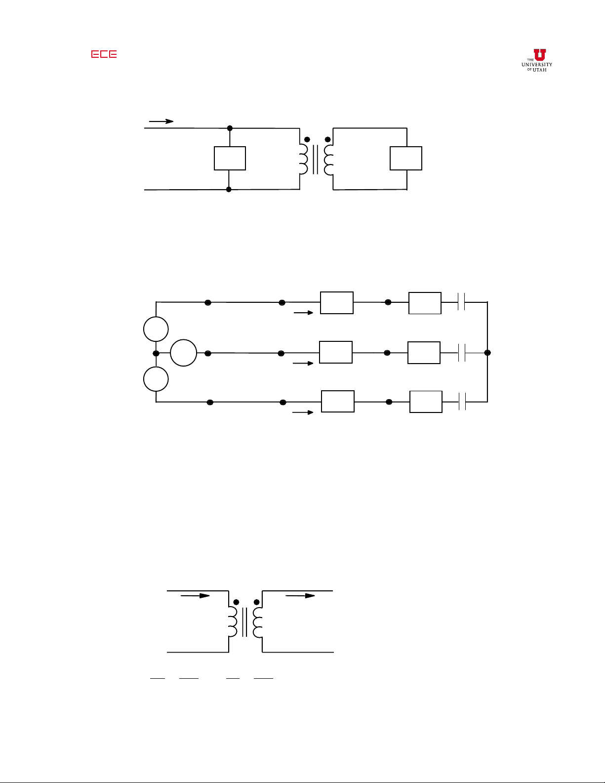
Z Z
V
I
V
Z
1 = (5 - j5)Ω Z 2 = (20 + j20)Ω
a. Find the input impedance, z in
= V
1
/ I
1 , for the above circuit.
b. Using z in from (a), find a numerical expression for V AB in the
circuit below.
A
B
C
V
V
V
I
I
I
a′n
c′n
b′n
Z
Z
Z
in
in
in
aA
bB
cC
a′
b′
c′
n
a
b
c
– + N
Z
Z
Z
line
line
line
-j12 Ω
-j12 Ω
-j12 Ω
Balanced three-phase system.
V
an
= 52 ∠ 0°V V
bn = 52 ∠ –120°A z line = j12 Ω
ans: a) z in
b) V AB
≈ 234 ∠–37.38° V
sol'n: (a) Transformer is ideal. To distinguish currents in the transformer itself from
other currents, we use a prime to denote the transformer currents. The
current flowing into the dot on the primary side is I ′ 1
, and the current
flowing out of the dot on the secondary side is I ′ 2
V
V
I ′
I ′
V
1
V
2
N
1
N
2
I^ ′
1
I ′
2
N
2
N
1
Using the above model, we can derive the formula (or we can just look up
the formula) for secondary impedance reflected into the primary:
z
r
N
1
N
2
2
z
2
Our model, given N 1 /N 2 = 1/2 turns ratio, is:
z 1
z r
V
5 − j 5 Ω
20 + j 20
Ω = 5 = j 5 Ω
I
I ′
z = z
1
z
r
= ( 5 − j 5 ) ( 5 + j 5 )Ω
z =
( 5 − j 5 )( 5 + j 5)
5 − j 5 + 5 + j 5
2
2
sol'n: (b) Our first step is to convert our circuit to a Y – Y form so we can use a single-
phase equivalent model. In this problem, the circuit is already in Y – Y form
and we may draw the single-phase equivalent directly:
A
V
I
a′n
Z
in
aA
a′
n
a
N
Z
line
-j12 Ω
We find V AN and then calculate V AB using phasor diagrams. We obtain
V
AN from the voltage divider formula:
V
AN
= V
a ′ n
z
in
− j 12 Ω
z
line
+ z
in
− j 12 Ω
V
AN
= 52 ∠ 0 ° V
5 Ω − j 12 Ω
j 12 Ω + 5 Ω − j 12 Ω
= 52 ∠ 0 ° V
5 Ω − j 12 Ω
V
AN
= 52 ∠ 0 ° V
We use a phasor diagram to relate V AN to V AB
. The diagram shows the
relationship between V AN and V AB , and we assume V AN has phase angle
zero so we can find the relative phase angle of V AB