

1
ECE 545—Digital System Design with VHDL
Bit-Counter ASM Example
2
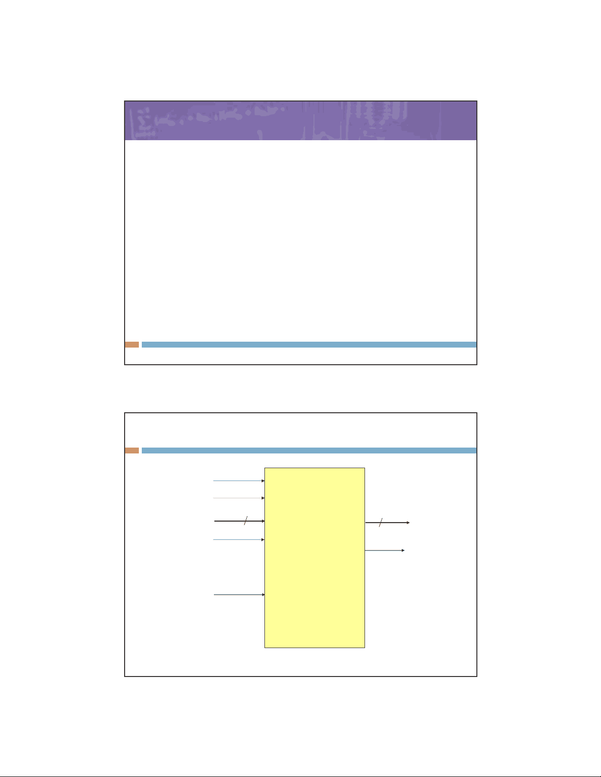
Bit-Counting – Required Interface
Bit-Counter
Clock
Resetn
Data N
B
log2(N)
Done
S
(0=transfer data
1=computations)
Specification: Count the number of 1’s in Data
LA

Study with the several resources on Docsity

Earn points by helping other students or get them with a premium plan

Prepare for your exams
Study with the several resources on Docsity
Earn points to download
Earn points by helping other students or get them with a premium plan
The design details of a bit-counter using vhdl, including pseudocode, high-level asm, datapath block diagram, and controller asm. The bit-counter is designed to count the number of 1's in an n-bit input data. The functionality of each port, the logic behind the design, and the step-by-step implementation.
Typology: Study notes
1 / 5

This page cannot be seen from the preview
Don't miss anything!
EB z
s
a (^) 0
Reset
(^0) s 1 S
Done
n